# COMBUSTION INSTABILITY IN LIQUID PROPELLANT ROCKETS:
Table of Contents:
- What Is Combustion Instability In Liquid Propellant Rockets?
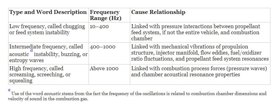
- Types Of Combustion Instability In Liquid Propellant Rockets
- Combustion Instability – Chugging / Feed System Instability
- Combustion Instability – Acoustic Instability / Buzzing / Entropy Waves
- Combustion Instability – Screaming / Screeching / Squealing
What Is Combustion Instability In Liquid Propellant Rockets?
Combustion instabilities are physical phenomena occurring in a reacting flow (e.g., a flame) in which some perturbations, even very small ones, grow and then become large enough to alter the features of the flow in some particular way. In many practical cases, the appearance of combustion instabilities is undesirable. When rocket combustion processes are not well controlled, combustion instabilities may grow and very quickly cause excessive pressure‐induced vibrational forces (that may break engine parts) or excessive heat transfer (that may melt thrust chamber parts).
The below table lists the principal types of combustion generated vibrations encountered in liquid rocket thrust chambers. Admittedly, liquid propellant rocket thrust chamber combustion is never perfectly smooth because minor fluctuations of pressure, temperature, and velocity are always present. When these fluctuations interact with the natural frequencies of the propellant feed system (with or without vehicle structure) or with the chamber acoustics, large periodic superimposed oscillations develop.
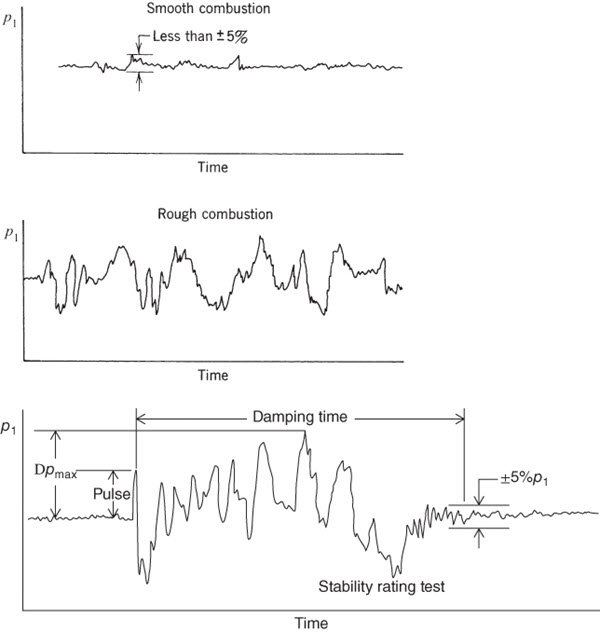
In normal rocket propulsion practice, smooth combustion is said to occur when pressure fluctuations during operation do not exceed ± 5% of the mean chamber pressure. Combustion that generates larger pressure fluctuations, as measured at chamber wall locations and occurring at completely random intervals is called rough combustion. Unstable combustion, or combustion instability, displays organized oscillations occurring at well‐defined intervals with pressure peaks that may be maintained, may increase, or may die out. These periodic peaks represent fairly large concentrations of vibratory energy and can be easily recognized against the random‐noise background using high‐frequency pressure measurements.
Typical Simplified Oscillograph Traces Of Chamber Pressure p1 With Time For Different Combustion Events
Types Of Combustion Instability In Liquid Propellant Rockets:
There are three basic types of combustion instability in liquid propellant rockets and are,
- Low Frequency – Chugging / Feed System Instability
- Intermediate Frequency – Acoustic Instability / Buzzing / Entropy Waves
- High Frequency – Screaming / Screeching / Squealing
1. Combustion Instability In Liquid Propellant Rockets – Chugging / Feed System Instability:
Chugging, the first type of combustion instability, stems mostly from the elastic nature of the feed systems and vehicle’s structures and/or from the imposition of propulsive forces upon the vehicle. Chugging in an engine or thrust chamber assembly may occur at a test facility or during flight, especially with low‐chamber‐pressure engines (100 to 500 psia). It may originate from propellant pump cavitation, gas entrapment in propellant flows, tank pressurization control fluctuations, and/or vibration of engine supports and propellant lines. It may also be caused by resonances in the engine feed system (such as oscillating bellows inducing periodic flow fluctuations) or by the coupling of structural and feed system frequencies.
When both the vehicle structure and the propellant liquid in the feed system have similar natural frequencies, then a coupling of forces occurs that may not only maintain but also strongly amplify existing oscillations. Propellant flow rate disturbances, usually at 10 to 50 Hz, give rise to such low‐frequency longitudinal combustion instabilities, producing longitudinal vibration modes in the vehicle. Pogo instability refers to a vehicle’s long‐feed pipe instability since it is similar to a pogo jumping stick motion. Pogo instabilities can occur in the large, long propellant feed lines of large vehicles such as space launch vehicles or in ballistic missiles.
Avoiding objectionable engine–vehicle coupled oscillations is best accomplished during initial vehicle design, in contrast to applying “fixes” later, as had been the case with rocket engines of older large flight vehicles. Analytical methods exist for understanding most vibration modes and damping tendencies of major vehicle components, including propellant tanks, tank pressurization systems, propellant flow lines, engines, and basic vehicle structures.
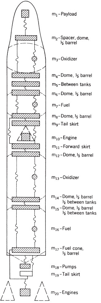
The below figure is a simplified spring–mass model of a typical two‐stage vehicle, illustrates the complexity of the analytical problem. Fortunately, most vibrational characteristics of the rocket assembly can be substantially controlled by introducing damping into major components or subassemblies. Techniques for damping pogo instabilities include the use of energy absorption devices in fluid flow lines, perforated tank liners, special tank supports, and properly designed engine, interstage, and payload support structures.
Diagram of a typical two‐stage vehicle spring–mass model used in analysis of pogo vibration in the vertical direction. The cross‐hatched areas represent masses and the wiggly lines indicate springs.
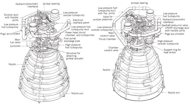
A partially gas‐filled, spherical, small pogo accumulator attached to the main oxidizer feed line has been used as an effective damping device. It was used in the oxidizer feed line of the Space Shuttle main engine (SSME) between the oxidizer booster pump and the main oxidizer pump.
2. Combustion Instability In Liquid Propellant Rockets – Acoustic Instability / Buzzing / Entropy Waves:
Buzzing, an intermediate frequency type of instability, seldom derives from pressure perturbations greater than 5% of the mean in the combustion chamber and is usually not accompanied by large vibratory energies. It is more often an annoying noise than a damaging effect, although the occurrence of buzzing may sometimes initiate high‐frequency instabilities. It is characteristic of a coupling between the combustion process and the flow in a portion of the propellant feed system.
Buzzing initiation is thought to originate from the combustion process itself. Acoustic resonances of the combustion chamber with some critical portion of the propellant flow system, sometimes originating in a pump, promote continuation of these buzzing effects. This type of instability seems to be more prevalent in medium‐size engines (2000 to 250,000 N thrust or about 500 to 60,000 lbf) than in larger engines.
3. Combustion Instability In Liquid Propellant Rockets – Screaming / Screeching / Squealing:
The third type of instability, screeching or screaming, produces high frequencies (4 to 20 kHz) and is the most perplexing and common feature in new engine development. Many liquid rocket engines and solid propellant motors experience some high‐frequency instability during their developmental phase. Since energy content increases with frequency, this type can be the most damaging, capable of destroying an engine in less than 1 sec.
Once encountered, it is often difficult to prove that any newly incorporated “fixes” or improvements will render the engine “stable” under all launch and flight conditions. Screeching may be treated as a phenomenon solely related to the combustion chamber and not generally influenced by feed systems or structures.
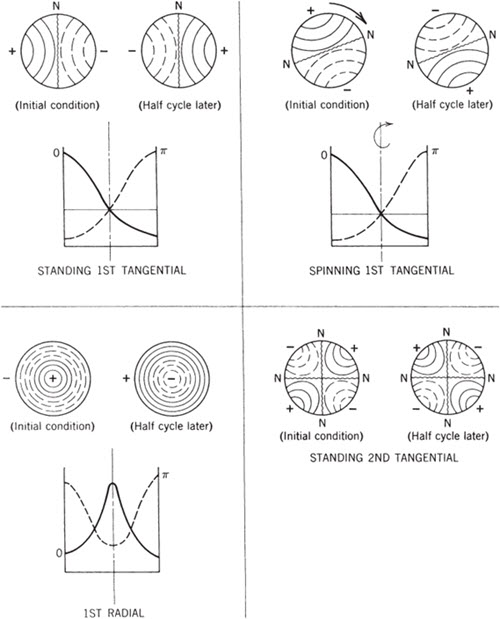
High‐frequency instabilities occur in two basic modes, longitudinal and transverse. The longitudinal mode (sometimes called organ pipe mode) propagates along axial planes of the combustion chamber, and its pressure waves are reflected at the injector face and at the converging nozzle entrance section. The transverse mode propagates along planes perpendicular to the chamber axis and can be broken down into tangential and radial modes. Transverse mode instabilities predominate in large liquid rockets, particularly in the vicinity of the injector.
The below figure shows pressure distributions at various time intervals in a combustion chamber of cylindrical cross section that is encountering transverse mode instabilities. Two kinds of wave form have been observed in tangential vibrations; one can be considered a standing wave because it remains in a fixed position while its pressure amplitude fluctuates; the other is a spinning or traveling tangential wave with an associated rotation of the whole vibratory system—this waveform can be visualized as maintaining constant amplitude while the wave rotates. Combinations of transverse and longitudinal modes may also occur and their frequency can also be estimated.
Simplified representation of transverse pressure oscillation modes at two time intervals in a cylindrical combustion chamber. The solid‐line curves indicate pressures greater than the normal or mean operating pressure and the dashed lines indicate lower pressures. The N–N lines show node locations for these wave modes.
Screeching is believed to be predominantly driven by acoustical‐energy‐stimulated variations in droplet vaporization and/or mixing, by local detonations, and by acoustic changes in combustion rates. Thus, with any assisting acoustic properties, once triggered, high‐frequency combustion instabilities can rapidly induce destructive modes. Invariably, any distinct boundary layer may disappear and heat transfer rates may increase by an order of magnitude causing metal melting and wall burn‐throughs, sometimes within less than 1 sec. Here, tangential modes appear to be the most damaging, with heat transfer rates during an instability often increasing 2 to 10 times and instantaneous pressure peaks about twice as high as with stable operation.
One source that possibly triggers high‐frequency pressure‐wave instabilities is a rocket combustion phenomenon called popping. Popping is an undesirable random high‐amplitude pressure disturbance that arises during the steady‐state operation of rocket engines that use hypergolic propellants. These “pops” exhibit some of the characteristics of a detonation wave. The pressure rise times are a few microseconds and the pressure ratios across the wave can be as high as 7:1.
Some combustion instabilities are induced by pulsations in the liquid flow originating at the turbopumps. Unsteady liquid flows may result from irregular cavitation at the leading edge of inducer impellers or main pump impellers. Also, when an impeller’s trailing edge passes a rib or stationary vane in the volute, a small pressure perturbation always results in the liquid as it travels downstream to the injector. These two types of pressure fluctuation can be greatly amplified if they coincide with the natural frequencies of combustion induced vibrations in the chamber. Also, liquid propellant feed systems may generate oscillations under certain conditions.
To find more topics on our website…
Do you want to refer wikipedia? Please click here…

