# COMBUSTION CHAMBER PROCESS:
Table of Contents:
- What Is Combustion Chamber?
- Combustion Chamber Process
- Factors Influencing Combustion Chamber Design
What Is Combustion Chamber?
Schematic Diagram Of An Open Cycle Gas Turbine

Combustion Chamber Process:
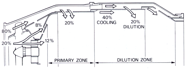
Combustion Chamber Processes – Air Separation Percentage Diagram

Approximately 20% of the air mass flow is taken in by the snout or entry section. Immediately downstream of the snout are swirl vanes and a perforated flare, through which air passes into the primary combustion zone. The swirling air induces a flow upstream of the center of the flame tube and promotes the desired re-circulation. The air not picked up by the snout flows into the annular space between the flame tube and the air casing. Through the wall of the flame tube body, adjacent to the combustion zone, are a selected number of secondary holes through which a further 20% of the main flow of air passes into the primary zone.
The air from the swirl vanes and that from the secondary air holes interacts and creates a region of low velocity recirculation. This takes the form of a vortex, which has the effect of stabilizing and anchoring the flame. It is arranged that the conical fuel spray from the nozzle intersect the recirculation vortex at its center. This action, together with the general turbulence in the primary zone, greatly assists in breaking up the fuel and mixing it with the incoming air. The temperature of the gases released by the combustion is about 1,800 – 2,000 0 C, which is far too hot for entry to the nozzle guide vanes of the turbine.
The air not used for combustion, which amounts to about 60% of the total airflow, is therefore introduced progressively into the flame tube. Approximately a third of this is used to lower the gas temperature in the dilution zone before it enters the turbine and the remainder is used for cooling the walls of the flame tube. This is achieved by a film of cooling air flowing along the inside surface of the flame tube wall, insulating it from the hot combustion gases.
Combustion should be completed before the dilution air enters the flame tube, otherwise the incoming air will cool the flame and incomplete combustion will result. An electric spark from an igniter plug initiates combustion and the flame is then self-sustained. The design of a combustion chamber and the method of adding the fuel may vary considerably, but the airflow distribution used to effect and maintain combustion is always very similar to that described.
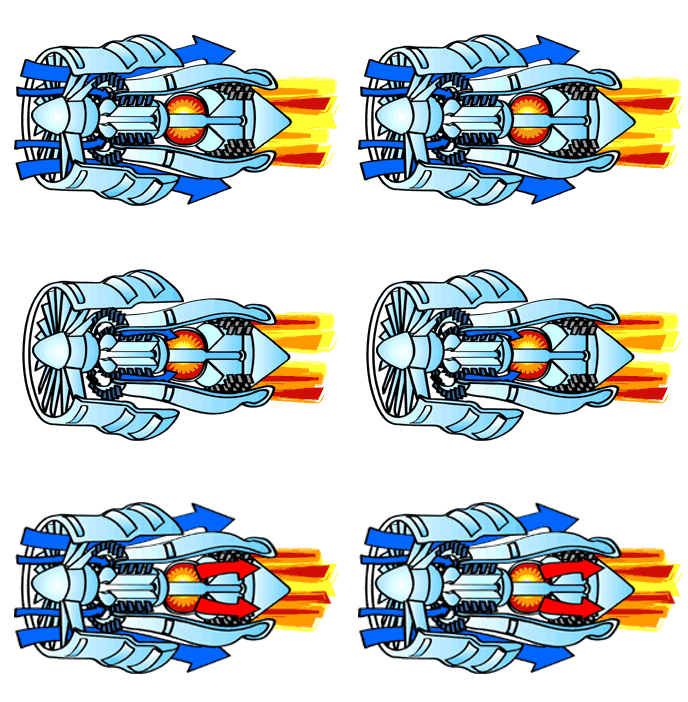
Combustion Chamber Process Animation

Factors Influencing Design (Combustion Chamber Process):
- Low turbine inlet temperature.
- Uniform temperature distribution at turbine inlet (i.e., to avoid local overheating of turbine blades).
- Stable operation even when factors like air velocity, A/F ratio & chamber pressure varies greatly, especially for aircraft engines (the limit is the ‘flameout’ of the combustion chamber) & at the event of a flame-out the combustor should be able to relight quickly.
- The formation of carbon deposits (‘coking’) must be avoided. Can damage the turbine if breaks free.
- Aircraft engines should avoid visible smoke as it hinders visibility in airports.
- Finally, pollutants like NOx, CO, unburned Hydrocarbons(UHCs) etc. should be limited.
