# THRUST VECTOR CONTROL:
Table of Contents:
- What Is Thrust Vector Control?
- Reasons For Thrust Vector Control
- Thrust Vector Control – Pitch, Yaw And Roll
- Thrust Vector Control With A Single Nozzle
Mechanical Deflection Of The Nozzle
Insertion Of Heat-Resistant Movable Bodies Into The Exhaust Jet
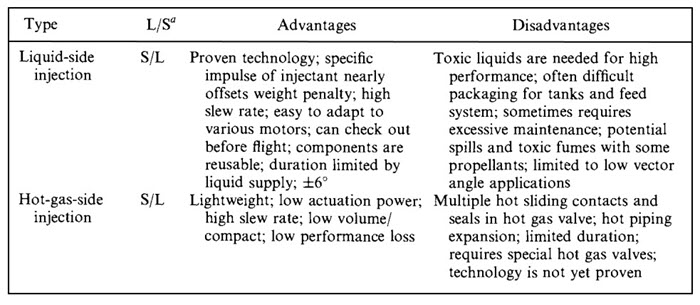
Injection Of Fluid Into The Side Of The Diverging Nozzle Section
Separate Thrust-Producing Devices - Schematic Diagrams of Eight Different Thrust Vector Control Mechanism
- Thrust Vector Control With Multiple Thrust Chambers Or Nozzles
What Is Thrust Vector Control?
In addition to providing a propulsive force to a flying vehicle, a rocket propulsion system can provide moments to rotate the flying vehicle and thus provide control of the vehicle’s attitude and flight path. By controlling the direction of the thrust vectors through the mechanisms, it is possible to control a vehicle’s pitch, yaw, and roll motions.
Thrust vector control is effective only while the propulsion system is operating and creating an exhaust jet. For the flight period, when a rocket propulsion system is not firing and therefore its Thrust Vector Control is inoperative, a separate mechanism needs to be provided to the flying vehicle for achieving control over its attitude or flight path.
Aerodynamic fins (fixed and movable) continue to be very effective for controlling vehicle flight within the earth’s atmosphere, and almost all weather rockets, antiaircraft missiles, and air-to-surface missiles use them. Even though aerodynamic control surfaces provide some additional drag, their effectiveness in terms of vehicle weight, turning moment, and actuating power consumption is difficult to surpass with any other flight control method.
Reasons For Thrust Vector Control:
- To willfully change a flight path or trajectory (e.g., changing the direction of the flight path of a target-seeking missile).
- To rotate the vehicle or change its attitude during powered flight.
- To correct for deviation from the intended trajectory or the attitude during powered flight.
- To correct for thrust misalignment of a fixed nozzle in the main propulsion system during its operation, when the main thrust vector misses the vehicle’s center of gravity.
Thrust Vector Control – Pitch, Yaw And Roll:
Pitch moments are those that raise or lower the nose of a vehicle; yaw moments turn the nose sideways; and roll moments are applied about the main axis of the flying vehicle.
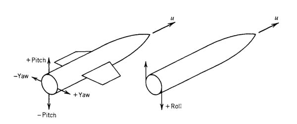
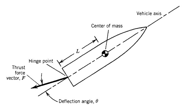
Usually, the thrust vector of the main rocket nozzle is in the direction of the vehicle axis and goes through the vehicle’s center of gravity. Thus it is possible to obtain pitch and yaw control moments by the simple deflection of the main rocket thrust vector; however, roll control usually requires the use of two or more rotary vanes or two or more separately hinged propulsion system nozzles. The below image explains the pitch moment obtained by a hinged thrust chamber or nozzle. The side force and the pitch moment vary as the sine of the effective angle of thrust vector deflection.
Thrust Vector Control With A Single Nozzle:
Many different mechanisms have been used successfully. They can be classified into four categories:
- Mechanical deflection of the nozzle or thrust chamber.
- Insertion of heat-resistant movable bodies into the exhaust jet; these experience aerodynamic forces and cause a deflection of a part of the exhaust gas flow.
- Injection of fluid into the side of the diverging nozzle section, causing an asymmetrical distortion of the supersonic exhaust flow.
- Separate thrust-producing devices that are not part of the main flow through the nozzle.
1. Mechanical Deflection Of The Nozzle:
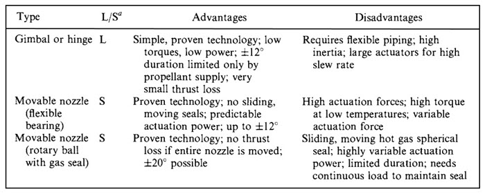
In the hinge or gimbal scheme (a hinge permits rotation about one axis only, whereas a gimbal is essentially a universal joint), the whole engine is pivoted on a bearing and thus the thrust vector is rotated. For small angles this scheme has negligible losses in specific impulse and is used in many vehicles. It requires a flexible set of propellant piping (bellows) to allow the propellant to flow from the tanks of the vehicle to the movable engine.
2. Insertion Of Heat-Resistant Movable Bodies Into The Exhaust Jet:
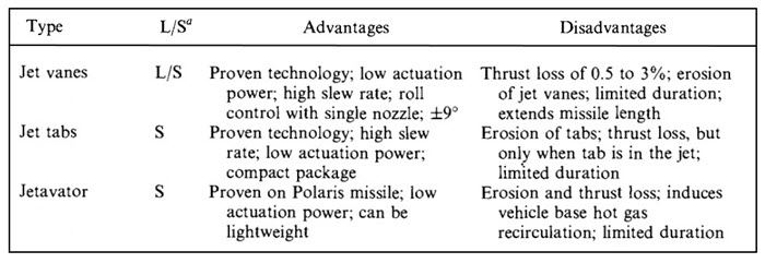
Jet vanes are pairs of heat-resistant, aerodynamic wing-shaped surfaces submerged in the exhaust jet of a fixed rocket nozzle. They were first used about 55 years ago. They cause extra drag (2 to 5% less Is; drag increases with larger vane deflections) and erosion of the vane material. Graphite jet vanes were used in the German V-2 missile in World War II and in the Scud missiles fired by Iraq in 1991. The advantage of having roll control with a single nozzle often outweighs the performance penalties.
3. Injection Of Fluid Into The Side Of The Diverging Nozzle Section:
The injection of secondary fluid through the wall of the nozzle into the main gas stream has the effect of forming oblique shocks in the nozzle diverging section, thus causing an unsymmetrical distribution of the main gas flow, which produces a side force. The secondary fluid can be stored liquid or gas from a separate hot gas generator (the gas would then still be sufficiently cool to be piped), a direct bleed from the chamber, or the injection of a catalyzed monopropellant. When the deflections are small, this is a low-loss scheme, but for large moments (large side forces) the amount of secondary fluid becomes excessive.
4. Separate Thrust-Producing Devices:
Small auxiliary thrust chambers were used in the Thor and early version of Atlas missiles. They provide roll control while the principal rocket engine operates. They are fed from the same feed system as the main rocket engine. This scheme is still used on some Russian booster rocket vehicles.

Schematic Diagrams of Eight Different Thrust Vector Control Mechanism:
Actuators and structural details are not shown. The letter L means it is used with liquid propellant rocket engines and S means it is used with solid propellant motors.
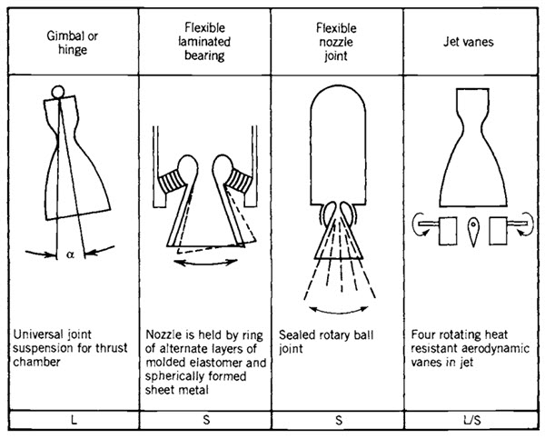
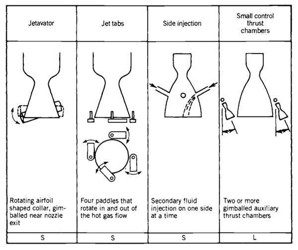
Of all the mechanical deflection types, the movable nozzles are the most efficient. They do not significantly reduce the thrust or the specific impulse and are weight-competitive with the other mechanical types. The flexible nozzle is a common type of Thrust Vector Control used with solid propellant motors. The molded, multilayer bearing pack acts as a seal, a load transfer bearing, and a viscoelastic flexure. It uses the deformation of a stacked set of doubly curved elastomeric (rubbery) layers between spherical metal sheets to carry the loads and allow an angular deflection of the nozzle axis.
The flexible seal nozzle has been used in launch vehicles and large strategic missiles, where the environmental temperature extremes are modest. At low temperature the elastomer becomes stiff and the actuation torques increase substantially, requiring a much larger actuation system. There are double seals to prevent leaks of hot gas and various insulators to keep the structure below 200°F or 93°C.
Thrust Vector Control With Multiple Thrust Chambers Or Nozzles:
Roll control can be obtained only if there are at least two separate vectorable nozzles, four fixed pulsing or throttled flow nozzles, or two jet vanes submerged in the exhaust gas from a single nozzle. Several concepts have been developed and flown that use two or more rocket engines or a single engine or motor with two or more actuated nozzles. Two fully gimballed thrust chambers or motor nozzles can provide roll control with very slight differential angular deflections.
For pitch and yaw control, the deflection would be larger, be of the same angle and direction for both nozzles, and the deflection magnitude would be the same for both nozzles. This can also be achieved with four hinged or gimballed nozzles.
The differential throttling concept shown in the below diagram has no gimbal and does not use any of the methods used with single nozzles. It has four fixed thrust chambers and their axes are almost parallel to and set off from the vehicle’s centerline. Two of the four thrust chambers are selectively throttled (typically the thrust is reduced by only 2 to 15 %). The four nozzles may be supplied from the same feed system or they may belong to four separate but identical rocket engines.
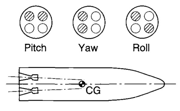
Differential throttling with four fixed-position thrust chambers can provide flight maneuvers. In this simple diagram the shaded nozzle exits indicate a throttled condition or reduced thrust. The larger forces from the unthrottled engines impose turning moments on the vehicle. For roll control the nozzles are slightly inclined and their individual thrust vectors do not go through the center of gravity of the vehicle.

What does L/S mean in reference to thrust vectoring?