# EROSIVE BURNING IN SOLID PROPELLANT ROCKETS:
Table of Contents:
- What Is Erosive Burning In Solid Propellant Rockets?
- Factors Affecting Erosive Burning In Solid Propellant Rockets
What Is Erosive Burning In Solid Propellant Rockets?
Erosive burning refers to any increase in the propellant burning rate caused by the high‐velocity flow of combustion gases across the burning propellant surface. It can seriously affect the performance of solid propellant rocket motors. It occurs primarily in port passages or in grain perforations as the combustion gases flow toward the nozzle; it is more likely to occur when the port passage cross‐sectional area A is not large relative to the throat area At , with a port‐to‐throat area ratio of 4 or less. High‐velocity gases near the burning surface and their turbulent mixing in the boundary layers increase the heat transfer to the solid propellant and thus increase the burning rate.
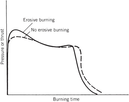
Erosive burning raises chamber pressure and thrust during the early portion of the burning, as shown in the below figure. As soon as burning enlarges the flow passage (without a major increase in burning area), the port area flow velocity is reduced and erosive burning diminishes until normal burning will again occur. Since propellant has been consumed more rapidly during the early erosive burning, there is also a reduction of burning time, and of flow and thrust at the end of burning.
Erosive burning also causes an early burnout of the web; for certain grain configurations, early web burnouts cause it to lose structural integrity resulting in thin web breakups which produce pieces of unburned propellant that are ejected thru the nozzle. Erosion can also occur at or near the end of the burning period with grains designed for progressive burning where the burning area is intentionally designed to increase in order to raise thrust and chamber pressure shortly before thrust termination. In general, only mild erosion can be tolerated and, in designing rocket motors, erosive burning is either avoided or controlled to be reproducible from one motor to the next.
Typical Simplified Pressure–Time Curve With And Without Erosive Burning
A plot with burning time on the horizontal axis, pressure of thrust on the vertical axis, a dashed line curve marked no erosive burning, and a solid line curve marked erosive burning.
A relatively simple model for erosive burning, based on heat transfer was first developed in 1956 by Lenoir and Robillard and has since been improved and used widely in motor performance calculations. It is based on adding together two burn rates: ro , which is primarily a function of pressure and ambient grain temperature without erosion, and re , the increase in burn rate due to gas erosion:
Here, G is the mass flow velocity per unit area in kg/m2‐sec, D is a characteristic dimension of the port passage (usually, D = 4Ap/S , where is the port area and S is its perimeter), ρb is the density of the unburned propellant (kg/m3), and α and β are empirically constants. Apparently, β is independent of propellant formulation and has a value of about 53 when r is in m/sec, p1 is in pascals, and G is in kg/m2‐sec. An expression of α has been determined from convective heat transfer considerations to be,
Here cp is the average specific heat at constant pressure of the combustion gases in kcal/kg‐K, μ the gas viscosity in kg/m‐sec, Pr the dimensionless Prandtl number (μcp /k) based on the molecular properties of the gases, k the thermal conductivity of the gas, cs the heat capacity of the solid propellant in kcal/kg‐K, T1 the combustion gas reaction absolute temperature, Ts the solid propellant surface temperature, and Tb the initial ambient temperature within the solid propellant grain.
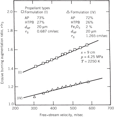
The below figure shows the augmentation ratio r/ro , or the ratio of the burning rate with and without erosive burning, as a function of gas velocity for two similar propellants, one of which has an iron oxide burn rate catalyst. Augmentation ratios up to 3 can be found in some motor designs. There is a pressure drop from the forward end to the aft end of the port passage, because static pressure is being converted to kinetic gas energy as the flow is accelerated. This pressure differential during erosive burning causes an extra axial load and deformation on the grain, which must be considered in the stress analysis.
Erosion rates or burn rate augmentations are not the same throughout the length of the port passage. Erosion is increased locally by flow turbulence resulting from discontinuities such as protrusions, edges of inhibitors, structural supports, or gaps between segmented grains.

Factors Affecting Erosive Burning In Solid Propellant Rockets:
Some of the factors that are affecting erosive burning in solid propellant rockets are,
- Pressure
- Propellant initial temperature
- Free stream gas temperature
- Normal burning rate
- Metal addition
- Compressibility
- Oxidizer particle size
- Rocket motor size
- Propellant characteristic
- Mass flux
- Reynolds number
To find more topics on our website…
Do you want to refer wikipedia? Please click here…

