# EJECTOR NOZZLE:
Table of Contents:
- What Is Ejector Nozzle?
- Variable Geometry Fixed Ejector Nozzle
- Variable Flap Ejector Nozzle
- Blow-In Door Ejector Nozzle
What Is Ejector Nozzle?
For subsonic flight, a simple fixed convergent nozzle is generally suitable for a broad range of flight conditions. However, in supersonic flight, the nozzle requirements are more severe and variable area capability is necessary. In addition, high temperatures associated with afterburning force the use of cooling air in the nozzle. There is an additional condition that must be considered, which is the need to minimize the additional drag attendant upon variable geometry nozzles. The manner in which the geometry of the aft regions of the aircraft fuselage is altered to accommodate nozzle geometry variations gives rise to varying degrees of so-called boat-tail drag.

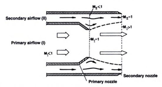
In design, the ejector nozzle features a convergent primary nozzle which is enclosed concentrically within a tube. The hot exhaust flow from the engine attains sonic velocity at the nozzle exit (M1=1), the highest Mach number possible with a convergent nozzle. Because of its high pressure, the jet will expand radially after exiting from the primary nozzle to supersonic Mach numbers (M1>1). Driven by suction from the primary gas-stream, a secondary flow is induced, the main task of which is to smooth the primary jet and thereby allow it to continuously accelerate to supersonic velocity.
Without a secondary flow, the primary jet would rapidly expand to ambient pressure by bursting. In this case, losses would be high and thrust low. Secondary flow, while damping the primary jet, is itself accelerated to sonic velocity at the nozzle exit (M1=1). The divergent section of the ejector nozzle is practically formed by a gaseous stream which at the same time provides a shielding to the nozzle outer casing, thus effectively preventing the hot gas from contacting the nozzle body.
Different Types of Ejector Nozzle:
The ejector nozzle exists in a number of variants. The most common types of ejector nozzle are as follows,
- Variable Geometry Fixed Ejector Nozzle
- Variable Flap Ejector Nozzle
- Blow-In Door Ejector Nozzle
1. Variable Geometry Fixed Ejector Nozzle:
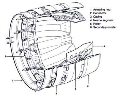
In its simplest version, it constitutes a fixed ejector of slightly divergent cross-section which encloses a variable-geometry primary nozzle. Such a nozzle was mounted to the augmentor tube of the General Electric J85 engine.
Variation of exit cross-section is accomplished by translating the nozzle axially with hydraulic actuators. Rollers of the ejector nozzle run in tracks of the primary nozzle segments. When the fixed-geometry nozzle is fully retracted, primary nozzle exit cross-section is a minimum. Conversely, when the fixed-geometry nozzle is fully extended, primary nozzle exit area is a maximum.
The benefits of this design are lightweight construction and trouble-free operation. The operational characteristics of this nozzle are essentially those of a convergent nozzle with limited supersonic performances and acceptable aerodynamic drag at subsonic speeds. Because, it is not a high-performance nozzle, its application is restricted to relatively simple combat aircraft.
Variable Geometry Fixed Ejector Nozzle

2. Variable Flap Ejector Nozzle:
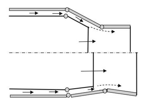
A much more efficient nozzle, albeit of more complicated construction, is the variable flap ejector nozzle. It has a variable geometry capability that provides for convergent nozzle operation at subsonic speed and convergent divergent nozzle operation with greater throat area for supersonic speeds. This type of nozzle is often called a long flap ejector nozzle, and variants of it have been used on the J79 and J93 engines used on the B-58, XB-70, F-4, and F-104 aircraft.
The long flaps provide for small boat-tail angle in the supersonic configuration, which is important in reducing fuselage drag while still providing for supersonic expansion within the nozzle. Bypass air again provides cooling for the nozzle. The convergent section of the nozzle comprises a number of overlapping segments, while the divergent section is formed by a secondary flow which is ducted around the core engine and exits through a variable-geometry nozzle.
The variable flap ejector nozzle is necessarily of higher weight and complexity, and the longer flaps are susceptible to aeroelastic problems, which can lead to destruction of the ejector. Of disadvantage is the large amount of secondary air required which results in high aerodynamic drag. Optimization for high-pressure ratios for supersonic afterburning dictates long flaps, which have reduced performance at low pressure ratios where shorter flaps would be superior. However, the requirements for supersonic flight were met by this type of ejector nozzle and were satisfactory for supersonic dash capability, that is, for intermittent use.
Variable Flap Ejector Nozzle at subsonic (upper view) and supersonic (lower view) speed

3. Blow-In Door Ejector Nozzle:
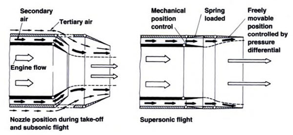
Even more sophisticated is the blow-in door ejector (BIDE) nozzle which utilizes “tertiary” air sucked in from outside, near the fuselage aft end. At high supersonic flight speed, the blow-in doors are closed because of the higher interior pressure; the secondary nozzle exit is in the fully open position. If flight speed is decreased to low supersonic velocities (around Mach 1.2), pressure in the nozzle is decreased automatically causing a gradual reduction of exit cross-section.
This process continues until the nozzle segments reach a stop at the minimum design exit cross-section. The aircraft is still in the transonic speed regime (between Mach 0.8 and 1.2). If flight speed is further reduced, pressure inside the nozzle will drop accordingly until the spring-loaded tertiary doors open, allowing air from outside to be sucked in. This nozzle configuration is maintained throughout the subsonic flight regime and for landing.
Blow-In Door Ejector Nozzle

Sucking-in considerable amounts of tertiary air requires flow ducts to be aerodynamically of high quality to keep losses low. The structural and mechanical construction of the BIDE ejector nozzle is relatively simple. The flaps are loaded from within by nozzle pressure so that they can rely on simple mechanical stops to limit their maximum opening. They can be permitted to float to intermediate positions dictated by the local conditions and have little unbalanced load to withstand.
Of course, any floating control surfaces must be selected properly to avoid oscillatory instability. In terms of weight and complexity, the BIDE falls between the simple ejector and the VFE. The BIDE has been used on the SR-71, the F-111, and the Concorde supersonic transport. The use of convergent–divergent iris nozzles, such as those on the F-14, has largely supplanted the VFE and BIDE nozzles in high-performance applications.
To find more topics on our website…
Do you want to refer wikipedia? Please click here…
