# INJECTORS - LIQUID PROPELLANT ROCKETS:
Table of Contents:
- What Is Injector?
- Types Of Injectors In Liquid Propellant Rockets
- Impinging-Stream-Type, Multi-Hole Injector
- Non-Impinging or Shower Head Injector
- Coaxial Hollow Post Injector
- Pintle Injector
What Is Injector?
The functions of the injector are similar to those of a carburetor of an internal combustion engine. The injector has to introduce and meter the flow of liquid propellants to the combustion chamber, cause the liquids to be broken up into small droplets (a process called atomization), and distribute and mix the propellants in such a manner that a correctly proportioned mixture of fuel and oxidizer will result, with uniform propellant mass flow and composition over the chamber cross section. This has been accomplished with different types of injector designs and elements.
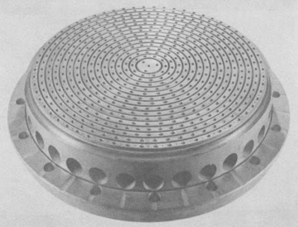
Injector With 90° Self-Impinging-Type Countersunk Doublet Injector Pattern
Types of Injectors In Liquid Propellant Rockets:
Injectors can be as simple as a number of small diameter holes arranged in carefully constructed patterns through which the fuel and oxidizer travel. The speed of the flow is determined by the square root of the pressure drop across the injectors, the shape of the hole and other details such as the density of the propellant.
The injection hole pattern on the face of the injector is closely related to the internal manifolds or feed passages within the injector. These provide for the distribution of the propellant from the injector inlet to all the injection holes. A large complex manifold volume allows low passage velocities and good distribution of flow over the cross section of the chamber. A small manifold volume allows for a lighter weight injector and reduces the amount of “dribble” flow after the main valves are shut.
The higher passage velocities cause a more uneven flow through different identical injection holes and thus a poorer distribution and wider local gas composition variation. Dribbling results in afterburning, which is an inefficient irregular combustion that gives a little “cutoff” thrust after valve closing. For applications with very accurate terminal vehicle velocity requirements, the cutoff impulse has to be very small and reproducible and often valves are built into the injector to minimize passage volume.
Some of the injectors used in liquid propellant rockets are as follows,
- Impinging-Stream-Type, Multi-Hole Injector
- Non-Impinging or Shower Head Injector
- Coaxial Hollow Post Injector
1. Impinging-Stream-Type, Multi-Hole Injector:
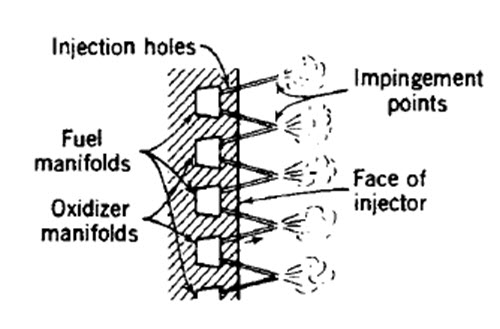
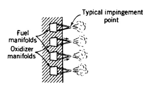
Impinging-stream-type, multiple-hole injectors are commonly used with oxygen-hydrocarbon and storable propellants. For unlike doublet patterns, the propellants are injected through a number of separate small holes in such a manner that the fuel and oxidizer streams impinge upon each other. Impingement forms thin liquid fans and aids atomization of the liquids into droplets, also aiding distribution. Impinging hole injectors are also used for like-on-like or self-impinging patterns (fuel-on-fuel and oxidizer-on-oxidizer).
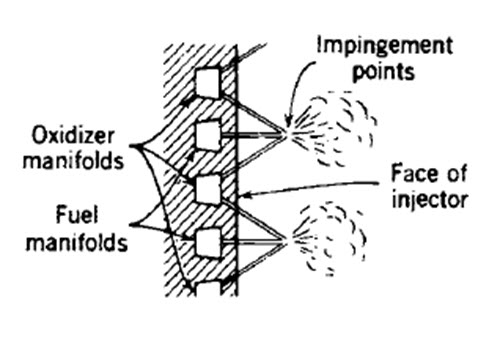
The two liquid streams then form a fan which breaks up into droplets. Unlike doublets work best when the hole size (more exactly, the volume flow) of the fuel is about equal to that of the oxidizer and the ignition delay is long enough to allow the formation of fans. For uneven volume flow the triplet pattern seems to be more effective.
Doublet Impinging Stream Pattern
Triplet Impinging Stream Pattern
Self-Impinging Stream Pattern
2. Non-Impinging or Shower Head Injector:
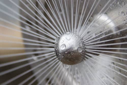
The non-impinging or shower head injector employs non-impinging streams of propellant usually emerging normal to the face of the injector. It relies on turbulence and diffusion to achieve mixing. The German World War II V-2 rocket used this type of injector. This type is now not used, because it requires a large chamber volume for good combustion. Sheet or spray-type injectors give cylindrical, conical, or other types of spray sheets; these sprays generally intersect and thereby promote mixing and atomization.
By varying the width of the sheet (through an axially moveable sleeve) it is possible to throttle the propellant flow over a wide range without excessive reduction in injector pressure drop. This type of variable area concentric tube injector was used on the descent engine of the Lunar Excursion Module and throttled over a 10:1 range of flow with only a very small change in mixture ratio.
Shower Head Stream Pattern
3. Coaxial Hollow Post Injector:
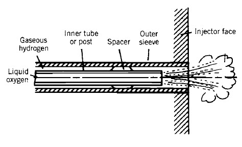
The coaxial hollow post injector has been used for liquid oxygen and gaseous hydrogen injectors by most domestic and foreign rocket designers. It works well when the liquid hydrogen has absorbed heat from cooling jackets and has been gasified. This gasified hydrogen flows at high speed (typically 330 m/sec or 1000 ft/sec); the liquid oxygen flows far more slowly (usually at less than 33 m/sec or 100 ft/sec) and the differential velocity causes a shear action, which helps to break up the oxygen stream into small droplets. The injector has a multiplicity of these coaxial posts on its face. This type of injector is not used with liquid storable bipropellants, in part because the pressure drop to achieve high velocity would become too high.
Coaxial Hollow Post Injector
4. Pintle Injector:
The pintle injector is a type of propellant injector for a bipropellant rocket engine. Like any other injector, its purpose is to ensure appropriate flow rate and intermixing of the propellants as they are forcibly injected under high pressure into the combustion chamber, so that an efficient and controlled combustion process can happen.
A pintle-based rocket engine can have a greater throttling range than one based on regular injectors, and will very rarely present acoustic combustion instabilities, because a pintle injector tends to create a self-stabilizing flow pattern. Therefore, pintle-based engines are specially suitable for applications that require deep, fast, and safe throttling, such as landers.
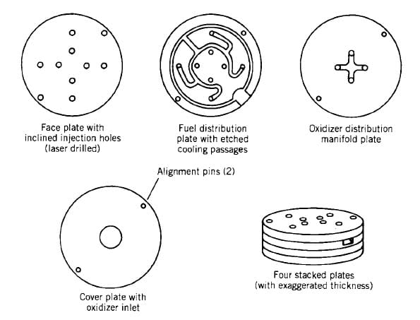
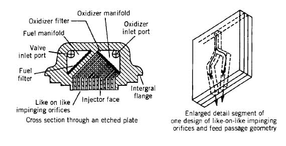
The original method of making injection holes was to carefully drill them and round out or chamfer their inlets. This is still being done today. It is difficult to align these holes accurately (for good impingement) and to avoid burrs and surface irregularities. One method that avoids these problems and allows a large number of small accurate injection orifices is to use multiple etched, very thin plates (often called platelets) that are then stacked and diffusion bonded together to form a monolithic structure as shown in the below figure.
Injector For Low Thrust With Four Impinging Unlike Doublet Liquid Streams | Plates Are Parallel To The Injector Face
Like-on-like Impinging Stream Injector With 144 Orifices | Plates Are perpendicular To The Injector Face
The photo-etched pattern on each of the individual plates or metal sheets then provides not only for many small injection orifices at the injector face, but also for internal distribution or flow passages in the injector and sometimes also for a fine-mesh filter inside the injector body. The platelets can be stacked parallel to or normal to the injector face. The finished injector has been called the platelet injector and has been patented by the Aerojet Propulsion Company.
To find more topics on our website…
Do you want to refer wikipedia? Please click here…

