# FLAME STABILIZATION:
Table of Contents:
- What Is Flame Stabilization?
- Parameters Influencing Flame Stabilization
- Flame Stabilization Methods
- Flame Stabilization Using A Bluff Body
- Flame Stabilization Using A Swirler
- Flame Stabilization Using A Pilot Flame
- Flame Stabilization Using Recirculation
- Flame Stabilization Using A Counter Flow Stabilizing Technique
- Flame Stabilization Using A Transverse Flow Technique
What Is Flame Stabilization?
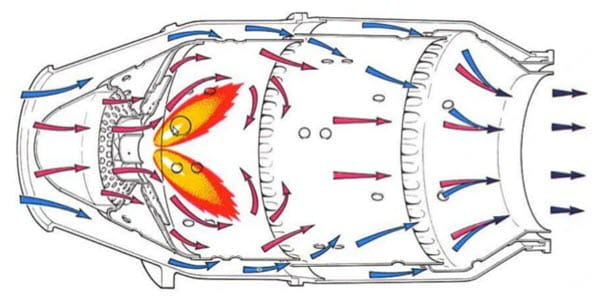
Flame stabilization is of fundamental importance in the design, the efficient performance and the reliable operation of high-speed propulsion systems. In gas turbines and other combustion equipment, the velocities at which the gases flow are much higher than the maximum flame speeds and the burner should be insensitive to large excess air as the power output is regulated by the fuel mass flow rate.
It is found that, the flow velocity and burning velocity are the most important factors that the flame stabilization depends on. The burning velocity should be equal to the flow velocity for a stationary flame front. In house and industrial applications flame stability is achieved by attaching the flame to a simple device known as a burner.
Flame stabilization is usually accomplished by causing some of the combustion products to recirculate and hence to continually ignite the fuel mixture. The hot recirculating gases transfer heat to the colder ones ignite those and initiate flame spread. The burnt gases transfer heat to the recirculation zone to balance the heat lost in igniting the combustible gas. Sufficient energy must be fed to the stabilization region to continuously ignite the coming gas flow.
Parameters Influencing Flame Stabilization:
There are many factors that affecting on the stabilization of flames are described here, these include:
- Blockage Effect
- Flame Holder Size
- Flame Holder Shape
- Fuel Type
- Stream Velocity
- Pressure
1. Blockage Effect:
If flame holder is located in a duct, which is the normal case, then an additional parameter controlling its stability characteristics is known as the blockage ratio, (BR). This is defined as the ratio of the area of projected flame holder to the cross sectional area of the duct. All stability theorems show that stability limit is widened as the characteristic dimension of the flame holder increases.
2. Flame Holder Size:
An increase in flame holder size improves stability by extending the residence time of reaction in the recirculation zone.
3. Flame Holder Shape:
The shape of flame holder affects its stability characteristics, which influences the size and shape of the wake region.
4. Fuel Type:
The fuel type has an effect on stability limit as for kerosene type fuel, it’s found that combustion can be sustained at leaner mixture strengths with fuels of lower specific gravity. The paraffin fuels will operate at lower fuel air ratio than aromatic fuels.
The stability is further improved with:
- The increase in fuel volatility.
- Finer atomization and reduction of the mean drop size of fuel.
5. Stream Velocity:
Any increase in stream velocity invariably has an adverse effect on flame stability. Any increase in velocity reduces the range of mixtures strengths over which combustion is possible and increases the weak extinction limit.
6. Pressure:
The increase in the reactants pressure always improves flame stability. The studies performed, by several investigators on bluff body flame holders in can-type, burners, and stirred reactors have fully confirmed the beneficial effect of increased pressure in extending the range of stable 5 operating conditions. For the gases mixture, the increase in the pressure expands the stability loop by enhancing the blowout velocity, especially for rich and near stoichiometric mixture.
Flame Stabilization Methods:
Free jet flames are hardly stable, so some mechanisms are needed to enhance the flammability limits of the flame such as using a bluff body, a swirler, a pilot flame, recirculation, a counter flow technique, by fixing putting flame holder in the combustible mixture flow.
1. Flame Stabilization Using A Bluff Body:
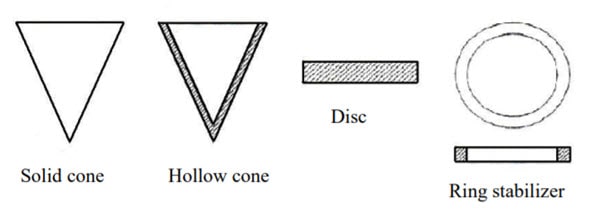
Bluff bodies are used to stabilize flames in high velocity flow in variety of propulsion and industrial combustion systems. These can be employed for supplementary firing in industrial boilers and heat recovery steam generators, and also used in ramjet and turbojet afterburner system. The usual shapes of the bluff bodies used are cylindrical rods, rectangular discs, baffles, cones or “vee” gutters, which produce in their wake a low velocity recirculated flow in which combustion can be initiated and maintained.
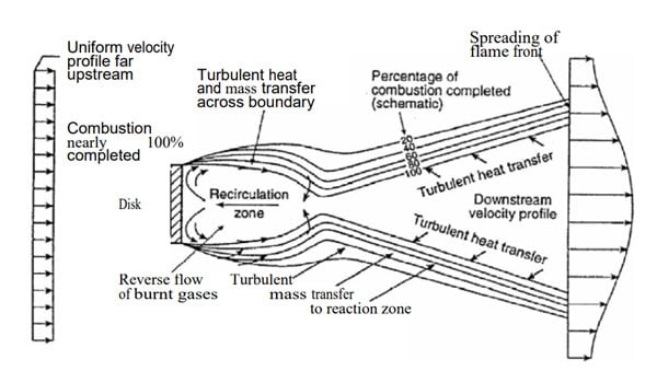
The propagation of flame to other regions is rendered possible by the transport of heat and radicals from the boundaries of the recirculation zone to the adjacent fresh mixture. Most of the understanding concepts of the flame stabilization process is referred to the pioneering studies carried out; these studies found that the wake behind the bluff body can be divided into the recirculation zone and the mixing zone that keeps the recirculation zone away from the unburned reactants.
The mixing zone, characterized by turbulent shear layers with large temperature gradients and rigorous chemical reaction, is fed by turbulent mixing processes with cool combustible gas coming from the approaching stream (based on the mixing model indicated by Williams).
Flame Stabilization Using A Bluff Body – Williams 1996
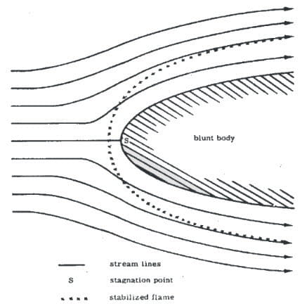
When a blunt body is placed in a high velocity reactant stream, the flow is greatly slowed down at the forward stagnation point to give ample opportunity for reactions to proceed to ignition. One major disadvantage of solid bluff bodies is the drag they exert on the flow and the resultant loss of thrust.
Flame Stabilization Using A Blunt Body
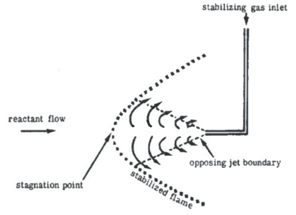
Campbell overcomes this drawback by employing an opposing gaseous jet in the reactant stream. It evolves as the opposing jet. The stream is slowed down and the flame is anchored as shown below. The blow‑off velocity is increased by increasing the injection pressure of the opposing jet and by increasing the temperature of the opposing jet gas.
Flame Stabilization Using An Opposing Jet
2. Flame Stabilization Using A Swirler:
A swirler is a number of curved swirl vanes have different angles normally 30, 45 and 60 degrees, which promotes the formation of recirculation zone and this is the essential mechanism for flame stabilization. Swirling flow can be produced either by tangential jet injections or by vane swirlers. The swirl angle determines the size and the strength of the recirculation zone and most of flame properties.
3. Flame Stabilization Using A Pilot Flame:
A pilot flame is an annular premixed flame located around the main jet flame used as a heat source to stabilize the main jet to the burner rim; the pilot flame is usually required to stabilize a jet flame due to its high exit velocity. A relative large pilot flame is used to produce a very lean jet flame.
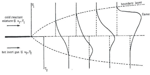
Suppose a pilot flame (as hot inert gas) is held adjacent to the cold reactant mixture flow issuing in the form of a high velocity jet. Heat and mass are transferred across the boundary of the two streams by diffusion and mixing. The reaction rate in the cold reactant mixture is thus enhanced shown in the below figure. Blow‑off would occur if the flow rate is greater the reaction rate in reactant mixture.
Flame Stabilization Using A Pilot Flame – The Marbel-Adamson Problem
4. Flame Stabilization Using Recirculation:
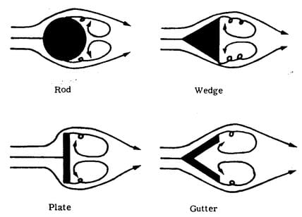
When the solid bluff body discussed above is of finite length in the direction of flow, the pressure distribution prevents the high velocity flow from keeping attached to the solid surface. Increasing pressure separates the boundary layer and causes eddy shedding in the “wake”. Under sufficiently fast flow conditions a (symmetric) recirculation pattern of flow is established behind the blunt body as shown below. The recirculation zone provides a station where reactions can take place.
Flame Stabilization Using Recirculation
5. Flame Stabilization Using A Counter Flow Stabilizing Technique:
A counter flow technique is to make the direction of the fuel jet in an opposite direction to the air flow, this technique reduces the flowing velocity of the combustible mixture against the burning velocity, also insures good mixing between the air and the fuel.
6. Flame Stabilization Using A Transverse Flow Technique:
The recent and new techniques to form flame stabilization takes place by transversing the flow stabilizing technique, flame stability by pulsed high voltage discharge, flame stability by magnetic source at discharge.

As an Avionic engineer, technician I have never been involved in engine theory and found this fascinating. I will never have to use it in any way but it will not be forgotten.