# COMBUSTION INSTABILITY IN SOLID PROPELLANT ROCKETS:
Table of Contents:
- What Is Combustion Instability In Solid Propellant Rockets?
- Types Of Combustion Instability In Solid Propellant Rockets
- Combustion Instability – Acoustic Instabilities
- Combustion Instability – Vortex Shedding Instability
What Is Combustion Instability In Solid Propellant Rockets?
Combustion instabilities are physical phenomena occurring in a reacting flow (e.g., a flame) in which some perturbations, even very small ones, grow and then become large enough to alter the features of the flow in some particular way. In many practical cases, the appearance of combustion instabilities is undesirable.
Types Of Combustion Instability In Solid Propellant Rockets:
There are two basic types of combustion instability and are,
- Sets of acoustic resonances or pressure oscillations, which can occur in any rocket motor.
- Vortex shedding phenomena, which occur only in relatively large segmented grains or in grains with circular slots.
1. Combustion Instability In Solid Propellant Rockets – Acoustic Instabilities:
When solid propellant rocket motors experience unstable combustion, pressures in interior gaseous cavities (made up by the volume of the port or perforations, fins, slots, conical or radial groves) oscillate by at least 5% and often by more than 30% of their nominal value. When such instability occurs, any heat transfer to the burning surfaces, the nozzle, and the insulated case walls greatly increases; the burning rate, chamber pressure, and thrust usually also increase causing total burning duration to decrease.
Changes in the thrust–time profile may cause significant changes in a vehicle’s flight path, which at times can lead to mission failure. If prolonged and with high vibration energy levels, an instability may cause hardware damage, such as overheating that leads to case and/or nozzle failure. Unstable conditions should be avoided and must be carefully investigated and remedied when they do occur during the motor’s development program. Final motor designs must be free of any instability.
There are fundamental differences between solid and liquid propellant combustion transient behavior. In liquid propellants, chamber geometries are fixed; liquids in feed systems and in injectors are physically not part of the oscillating gases in the combustion chamber but may interact strongly with pressure fluctuations. In solid propellant motors, the geometry of the oscillating cavity increases in size as burning proceeds and there are other strong damping factors, such as solid particles and energy‐absorbing viscoelastic materials.
In general, combustion instability problems do not occur frequently or in every motor development and, when they do occur, they are rarely the cause of motor failures or disintegrations. Nevertheless, drastic failures have occurred.
While acoustically “softer” than a liquid rocket combustion chamber, the combustion cavity of a solid propellant rocket is still a low‐loss acoustical cavity containing a very large acoustical energy source, the combustion process itself. Even small fractions of the energy released by combustion are more than sufficient to drive pressure vibrations to an unacceptable level.
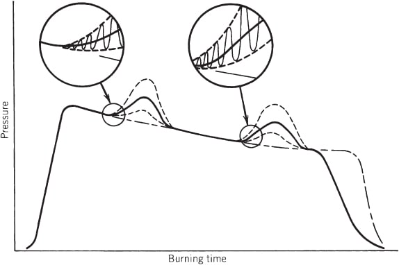
Several combustion instabilities can occur spontaneously, often at some particular time during the motor burn period, a phenomenon usually repeatable in identical motors. Both longitudinal and transverse waves (radial and tangential) can occur. The below figure shows a pressure–time profile with typical instabilities. As pressure oscillations increase in magnitude, thrust and burning rate also increase. Oscillating frequencies seem to be a function of cavity geometry, propellant composition, pressure, and internal flame field.
As the internal grain cavity enlarges and (some) oscillation frequencies and local velocities during the normal burning process change, oscillations often abate and disappear. The time and severity of vibrations due to combustion tend to change with ambient grain temperature prior to motor operation.
The above simplified diagram shows two periods of combustion instability in the pressure–time history, with enlargements of two sections of this curve. The dashed lines show the upper and lower boundaries of the high‐frequency pressure oscillations, and the dot‐dash curve is the behavior without instability after a slight change in propellant formulation. The vibration period shows a rise in the mean pressure. With vibration, the effective burning time is reduced and the average thrust is higher but total impulse remains unchanged.
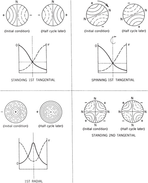
For simple grains within cylindrical port areas, the resonant transverse mode oscillations (tangential and radial) correspond roughly to those shown in the below figure for liquid propellant thrust chambers. The longitudinal or axial modes, usually at a lower frequency, represent an acoustic wave traveling parallel to the motor axis between the forward end of the perforation and the convergent nozzle section. Harmonic frequencies of these basic vibration modes may also be excited.
Internal cavities can become very complex since they may include igniter cases, movable as well as submerged nozzles, fins, cones, slots, star‐shaped perforations, and/or other shapes; determination of the resonant frequencies of complicated cavities is always challenging. Furthermore, the geometry of the internal resonating cavity changes continually as the burning propellant surfaces recede; as the cavity volume becomes larger, the transverse oscillation frequencies are reduced.
The above image shows the representation of transverse pressure oscillation modes at two time intervals in a cylindrical combustion chamber. The solid line curves indicate pressures greater than the normal or mean operating pressure and the dashed lines indicate lower pressures. The N-N lines show the node locations for these wave modes.
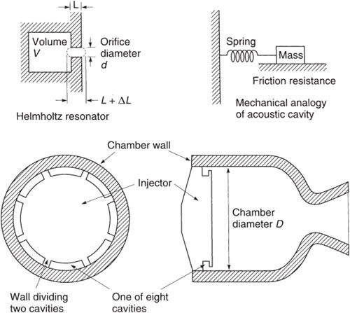
The bulk mode, also known as the Helmholtz mode, L* mode, or chuffing mode, is not a wave mode as described above. It occurs at relatively low frequencies (typically below 150 Hz and sometimes below 1 Hz), and pressures remain essentially uniform throughout the volume. The unsteady velocity is close to zero, but pressures do rise and fall. The gas motion (in and out of the nozzle) corresponds to the classical Helmholtz resonator mode, similar to exciting a tone when blowing across the open mouth of a bottle . It occurs at low values of L, sometimes during the ignition period, and disappears as the motor internal volume enlarges or the chamber pressure increases.
Chuffing relates to the periodic low‐frequency discharge of a bushy, unsteady flame of short duration (typically less than 1 sec) followed by periods of no visible flame, during which slow outgassing and vaporization of the solid propellant accumulates hot gas in the chamber. This often occurs near the end of burning. The motor experiences spurts of combustion and consequent pressure buildup followed by periods of essentially no flow with nearly ambient pressure. Such dormant periods can extend for a fraction of a second to a few seconds.
Diagram of acoustic energy absorber cavities at the periphery of an injector. In this thrust chamber the cavity restriction is a slot (in the shape of sections of a circular arc) and not a hole. Details of the chamber cooling channels, injector holes, or internal feed passages are not shown.
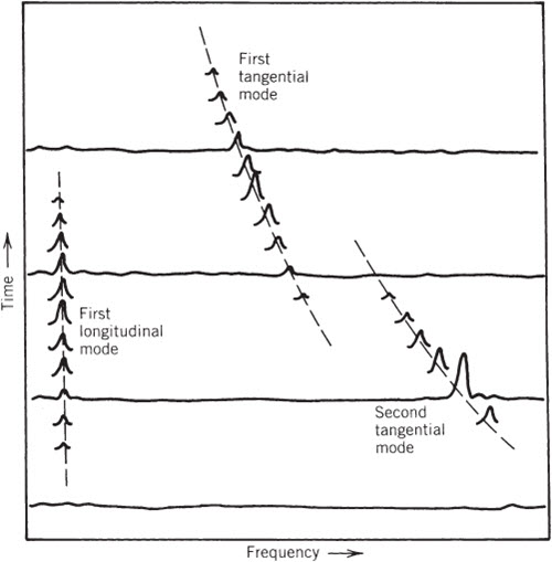
A useful method of visualizing unstable pressure waves is shown in the below figure. It consists of Fourier‐ analysis sets of the measured pressure vibration spectrum, each taken at a different burning time and displayed at successive vertical positions on a time scale, thus providing a map of amplitude versus frequency versus burning time. The below diagram shows a low‐frequency longitudinal or axial mode and two tangential modes, whose frequencies are reduced in time by the enlargement of the cavity; it also shows the timing of different vibrations, and their onset and demise.
Simplified example of mode frequency display also called a “waterfall” diagram of a rocket motor firing. Only a few complete time–frequency curves are shown; for ease of visualization the other time lines are partly omitted except near the resonating frequencies. The height of each wave is proportional to pressure. As the cavity volume increases, the frequencies of the transverse modes decrease. The frequency of the longitudinal mode (aligned with the cavity center‐line) does not change with time.
Initiation or triggering conditions for any particular vibration mode is still not well understood but has to do with the energetics of combustion at the propellant surface. A sudden change in pressure can be a trigger, such as when a piece of broken‐off insulation or unburned propellant flows through the nozzle, temporarily blocking all or a part of its flow area (causing a momentary pressure rise). Structural vibrations are known to induce instability caused by the physical movement of the grain in and out of the flame zone; this effect is similar to the way acoustic waves couple with the propellant response function.
The balance between amplifying and damping factors shifts during burning and this may cause either growth or abatement of specific modes of vibration. The response in a solid propellant relates to changes in gaseous mass production and in energy release at the burning surface when stimulated by pressure perturbations. When a momentary high‐pressure peak occurs at a burning surface, it increases the instantaneous heat transfer and thus the burning rate, causing the mass flow from that surface to also increase. Velocity perturbations along the burning surface are also believed to cause changes in mass flow. The following are phenomena that contribute to amplifying the vibrations or to gains in acoustic energy.
- The combustion process’ dynamic response to flow disturbances or oscillations in the burning rate. This response can be determined from tests with T‐burners as described on the following pages. The response function depends on the frequency of these perturbations and on propellant formulation. Combustion response may not be in phase with the disturbance.
- Interactions of flow oscillations with the main flow, similar to the operation of musical wind instruments or sirens.
- The fluid‐dynamic influence of vortexes.
Phenomena that contribute to diminishing vibrations or damping are energy‐absorbing processes; they include the following:
- Viscous damping in the boundary layers at the walls or propellant surfaces.
- Damping by particles or droplets flowing in oscillating gas/vapor flows, which is often substantial. These particles accelerate and decelerate, being “dragged” along by the motion of the gas, a viscous flow process that absorbs energy. The attenuation for each particular vibration frequency has an optimum at a particular particle size; high damping for low‐frequency oscillation (large motors) occurs with relatively large solid particles (8 to 20 µm); for small motors or high‐frequency waves the highest damping occurs with small particles (2 to 6 µm). Attenuation drops off sharply when the particle size distribution in the combustion gas is not concentrated near the optimum for damping.
- Energy from longitudinal and mixed transverse/longitudinal waves is lost out via the nozzle exhaust. Energy from purely transverse waves does not appear to dampen by this mechanism.
- Acoustic energy is absorbed by the viscoelastic solid propellant, insulator, and at the motor case; its magnitude is difficult to estimate.
2. Combustion Instability In Solid Propellant Rockets – Vortex Shedding Instability:
This instability is associated with surface burning of the grain at inner‐slots. Large segmented rocket motors have slots between segments, and some grain configurations have slots that intersect the centerline of the grain. The below figure shows hot gases from burning slot or step surfaces entering the main flow in the perforation or central cavity of the grain. Hot gases from slots then turn into a direction toward the nozzle. Flow from these side streams restricts the flow emanating from the upstream side of the perforation and, in effect, reduces the port area. Such restrictions cause the upstream port pressures to rise, sometimes substantially.
This interaction of two subsonic gas flows causes turbulence; vortices form and are periodically shed or allowed to flow downstream, thereby causing unstable flow patterns. These shed vortices can also interact with existing acoustic instabilities. The remedy is usually to apply inhibitors to some of the burning surfaces or to change the grain geometry—for example, increasing the width of a slot reduces the local velocities and the vortices become less pronounced.
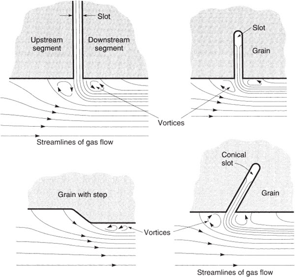
Vortex Shedding – Combustion Instability
Sketches of four partial grain sections each with a slot or a step. Heavy lines identify the burning surfaces. The flow patterns result in the formation of vortices. The shedding of these vortices can induce flow oscillations and pressure instabilities.
Several types of circumferential slots are illustrated in the above figure; when improperly designed, they produce noticeable pressure drops across the slot, causing propellant deflection, which may lead to propellant breakup and motor failure due to overpressures.
To find more topics on our website…
Do you want to refer wikipedia? Please click here…

