# COMBUSTION CHAMBER PERFORMANCE:
What Is Combustion Chamber Performance?
The combustion chamber performance can be assessed on the following parameters.
- Pressure Loss
- Combustion Efficiency
- Outlet Temperature Distribution
- Stability Limits
- Combustion Intensity
1. Pressure Loss (Combustion Chamber Performance):
Combustion chamber pressure loss is due to skin friction and turbulence and due to the rise in temperature due to combustion.
Hot or Fundamental Loss:
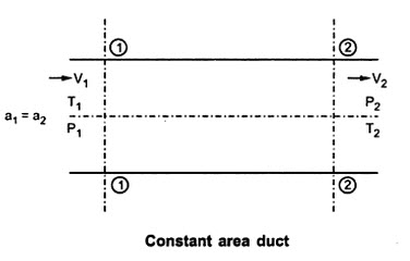
It is drop of stagnation pressure associated with rise in temperature due to combustion. Due to rise in temperature, density decreases and consequently velocity and momentum of the stream increases. To impact the increase in momentum, pressure force (ΔP x A∆) must be present. Consider a constant area duct, with heated gas stream flowing without friction.
The fundamental pressure loss for any rise in temperature can be predicted with the aid of the Rayleigh line functions. The momentum equation for one dimensional functionless flow in constant cross-sectional area duct.
For incompressible flow, the stagnation pressure is given by,
(P0)2 static pressure at exit and (P0)1 static pressure at inlet.
Also by applying continuity equation,
Substitute the value of (P2 – P1) from equation 1 in equation 2 we get,
At section 1-1, where air from diffuser with reduced velocity to V1 enters combustion duct, inlet dynamic heat of flow = ρ (V1²/2)
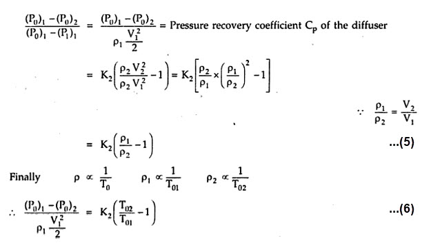
Loss of stagnation pressure in the constant area duct is a fraction of inlet dynamic head.
Assumption of incompressible flow and constant area duct are not true for a combustion chamber, still the result is sufficiently accurate for fundamental loss.
Cold Loss:
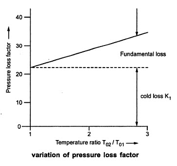
It is pressure loss in the combustion chamber due to skin friction. It is measured by pitot traverses at inlet and outlet with no combustion taking place. To achieve the proper mixing of fuel and air, turbulence is created in the combustion chamber with the help of swirl vanes. This turbulence contributes high frictional losses. Turbulence in the secondary and dilution zone is due to the jets of secondary and dilution air. The frictional loss is denoted by K1. Thus, overall stagnation pressure loss in the combustion chamber is sum of the fundamental loss and frictional loss.
Experimentally the pressure loss factor is expressed as,
When is test is conducted on a combustion chamber from cold run and hot run equation 7 can establish the pressure loss in the chamber over a wide range of conditions of mass flow, pressure ratio and fuel input.
PLF at design operating conditions for tubular combustion chamber is 35, for turbo-annular 25 and annular 18 respectively.
Overall Total Pressure Loss:
The overall total pressure loss of the combustion chamber is sum of inlet diffuser loss, burner dome and liner loss and momentum loss resulting from main burner flow acceleration due to increase in total gas temperature. It is normally expressed as a percentage of the compressor discharge pressure. It is normally 2 to 5%.
Combustion chamber pressure loss is necessary from design point of view (Pattern factor and effective cooling, etc.) and flame stabilization considerations. However, total pressure loss also have effect on engine thrust and thrust specific fuel consumption.
2. Combustion Efficiency (Combustion Chamber Performance):
Propulsion system fuel consumption has a direct effect on aircraft system range, payload and operating cost, it is imperative that design point combustion efficiency be close to 100% as possible. Combustion efficiency calculations based on chemical analysis of the combustion products is a trouble some and hectic task i.e. calculating actual energy released during combustion and theoretical quantity available.
Therefore, combustion efficiency is calculated on assumptions that the fuel is completely burnt and combustion efficiency is expressed as,
In alternative method, combustion efficiency is expressed as,
Neither definition is quite the same as the fundamental definition based on the ratio of actual energy released to the theoretical quantity obtainable. ηb differs from it because of the small additional heat capacity of the products arising from the increase in fuel needed to produce the given temperature.
But in actual practice combustion is nearly complete 98-99%, the efficiency is difficult to measure accurately and the three definitions of efficiency yield virtually the same result.
3. Outlet Temperature Distribution (Combustion Chamber Performance):
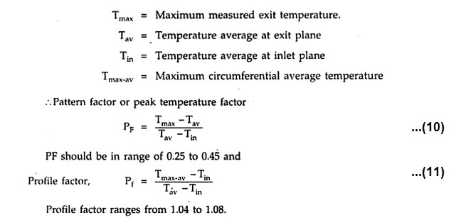
The combustion efficiency and pressure loss in the combustion chamber are related to the temperature uniformity of the combustion gases at the entry of the turbine. Temperature at the burner exit is measured by high temperature thermocouple.
Pattern factor and Profile factor are important main combustion design parameters. They describe the possible thermal impact on the turbine and are critical factors in matching the main burner and their components, if ranges of PF and Pf is not achieved, combustor life will be shorter.
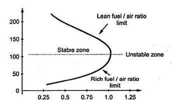
4. Stability Limit (Combustion Chamber Performance):
For any combustion, the flame will be stable depending on fuel/air ratio quality. Flame may blow out at lean fuel/air or at rich fuel/air mixture. This is taken as limit of stability, in which flame will hold. Normally instability will occur before the lean or rich fuel/air ratio limit is reached. Instability of flame indicates poor combustion, sets up aerodynamic vibrations which ultimately reduces combustion chamber life and causes blade vibrations.
Combustion stability —> The ability of the combustion process to sustain itself in a continuous manner.
Combustion stability depends on mass flow rate, combustion volume and pressure along with fuel/air ratio. All these are combined into the Combustor Loading Parameter (CLP) which is defined as
To have a stable flame, the velocity of the mixture must be maintained within certain limits. If the velocity is too high, the flame will be blown out the exit and if the velocity is too low, the flame will travel upstream and be extinguished. Normally the combustion chambers are designed with an inlet air velocity not exceeding 80 m/s at design load.
5. Combustion Intensity (Combustion Chamber Performance):
Combustion intensity determines the size of combustion chamber. Rate of heat release can be found by equation mf x Qnet . p , where m is the the air mass flow of its fuel/air ratio and Qnet . p is net calorific value of the fuel. The combustion chamber pressure, number of molecular collisions per unit time, unit volume which have an energy exceeding a certain activation value E also decides rate of reaction (r).
If ρ is submitted in above equation in terms of P and T and equation is simplified we get,
If hydrocarbon fuel is burnt in air, theoretical exponent 2 will apply to complex set of reactions. But experiments with homogeneous mixtures in stoichiometric proportions suggest that exponent should be 1.8.
Combustion intensity is ratio of heat release rate to the product of combustion volume and pressure.
Lower the combustion intensity easier to design combustion system. The combustion intensity is much higher for the main combustor of a turbojet (11150 MW/m) compared to a typical steam power plant (2.8 MW/m). Thus turbojet engine combustor design is more complex.
To find more topics on our website…
Do you want to refer wikipedia? Please click here…

