# PROPELLANT GRAIN DESIGN CONSIDERATIONS:
Table of Contents:
- What Is Propellant Grain?
- Propellant Grain Design Considerations
- Propellant Grain Requirements
- Different Configurations Of Propellant Grain
- Characteristics Of Propellant Grain Configurations
What Is Propellant Grain?
The grain is the shaped mass of processed solid propellant inside the rocket motor. The material and geometrical configuration of the grain govern motor performance characteristics. Propellant grains are cast, molded, or extruded bodies and their appearance and feel is similar to that of hard rubber or plastic. Once ignited, the grain will burn on all its exposed surfaces forming hot gases that are then exhausted through a nozzle. Most rocket motors have a single grain. A few have more than one grain inside a single case or chamber, and very few grains have segments made of different propellant composition (e.g., to allow different burning rates).
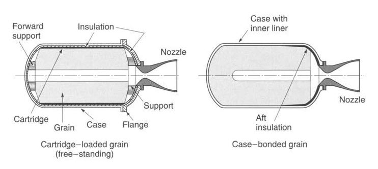
There are two methods of holding the grain in its case, as shown in the below figure. Cartridge‐loaded or freestanding grains are manufactured separately from the case (by extrusion or by casting into a cylindrical mold or cartridge) and then loaded into or assembled into the case. In case‐bonded grains, the case is used as a mold and the propellant is cast directly into the case and is bonded to the case, its liner or case insulation.
Freestanding grains can more easily be replaced when the propellant grain has aged excessively. Cartridge‐loaded grains are used in some small tactical missiles and a few medium‐sized rocket motors. They often have a lower cost and are easier to inspect. Case‐bonded grains give a somewhat better performance, a little less inert mass (no holding device, support pads, and less insulation), and a better volumetric loading fraction, but are more highly stressed and often somewhat more difficult and expensive to manufacture. Today almost all larger motors and many tactical missile motors use case bonding.
Schematic Diagrams Of A Freestanding (or Cartridge‐Loaded) And A Case‐bonded Grain
Propellant Grain Design Considerations:
Propellant Grain Requirements:
- Rocket motor requirements can be determined from the flight mission. These have to be known before the grain can be designed. They are usually established by the vehicle designers. Motor requirements can include total impulse, desired thrust–time curve and tolerance thereon, motor mass, ambient temperature limits during storage and operation, available vehicle volume or envelope, desired location or movement of rocket motor’s center of gravity, and accelerations caused by vehicle forces (vibration, bending, aerodynamic loads, etc.).
- The grain geometry is selected to fit motor requirements; it should be compact efficiently using the available volume, have an appropriate burn surface versus time profile to match the desired thrust–time curve, and avoid or predictably control possible erosive burning (many motors with progressive burning can tolerate short periods of erosive burning). Any remaining unburned propellant slivers, and often also the shift of the center of gravity during burning, should be minimized.
- The propellant is usually selected on the basis of its performance capability (e.g., characteristic velocity c*), mechanical properties (e.g., strength), ballistic properties (e.g., burning rate r), manufacturing characteristics, exhaust plume characteristics, and aging properties. If necessary, the propellant formulation may be slightly altered or “tailored” to fit more exactly the required burning time or grain geometry.
- Grain structural integrity, including its liner and/or insulator, must be analyzed to assure that the grain will not fail from stress or strain under all conditions of loading, acceleration, or thermal stress. Grain geometry can be changed to reduce excessive stresses.
- Any internal cavity volume made of perforations, slots, ports, and fins increases with burning time. These cavities need to be evaluated for resonance, vibration damping, and combustion stability.
- The processing of the grain and the fabrication of the propellant should be repeatable, simple, low cost and only cause acceptable thermal stresses.
Different Configurations Of Propellant Grain:
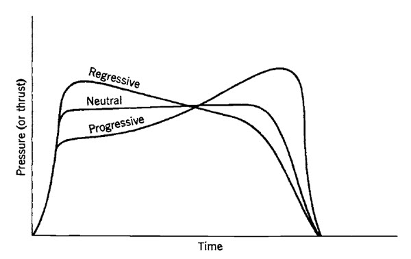
Though grain configuration designs aim to satisfy most of these requirements, there are cases when some of the six above categories can only be partially met. Grain geometry is crucial in its design. For a neutral burning grain (nearly constant thrust), for example, the burning surface Ab has to remain sufficiently constant, and for a regressive burning grain the burning area has to diminish during the burning time.
As a result of rocket motor developments of the past five decades, many grain configurations are available to motor designers. As new methods evolved for increasing the propellant burning rate, the number of configurations needed decreased. Current designs concentrate on relatively few configurations, since the needs of a wide variety of solid rocket motor applications can now be fulfilled by combining known configurations or by slightly altering a classical configuration. The trend has been to discontinue configurations that give weak grains or which form cracks more readily, or produce high sliver residues, or have a low volumetric loading fraction, or are more expensive to manufacture.
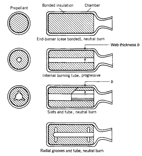
The results of propellant burning on internal surface areas are readily apparent for simple geometric shapes such as rods, tubes, wedges, and slots, as shown in the top four configurations in the below figure. Other basic surface shapes burn as follows: external burning rod—regressive; external burning wedge—regressive.
Classification Of Grains According To Their Pressure–Time Characteristics
Simplified Diagrams Of Several Grain Configurations
Typical Common Grain Configurations Using Combinations Of Two Basic Shapes For The Grain Cavity
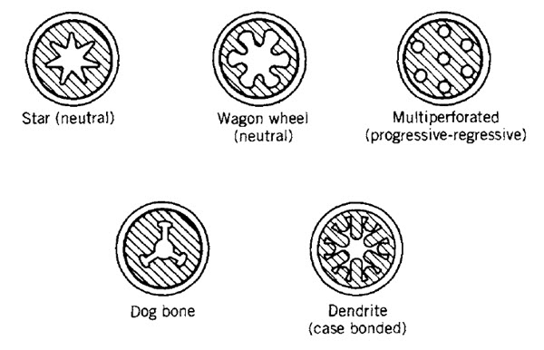
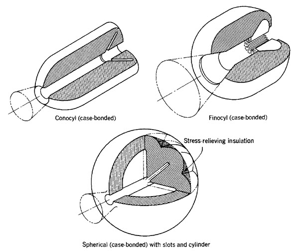
Most propellant grains combine two or more of these basic surfaces to obtain the desired burning characteristic. The star perforation, for example, combines the wedge and the internal burning tube. The above figure indicates typical single grains with combinations of two basic shapes. The term conocyl is a contraction of the words cone and cylinder. A finocyl has fins on a cylinder.
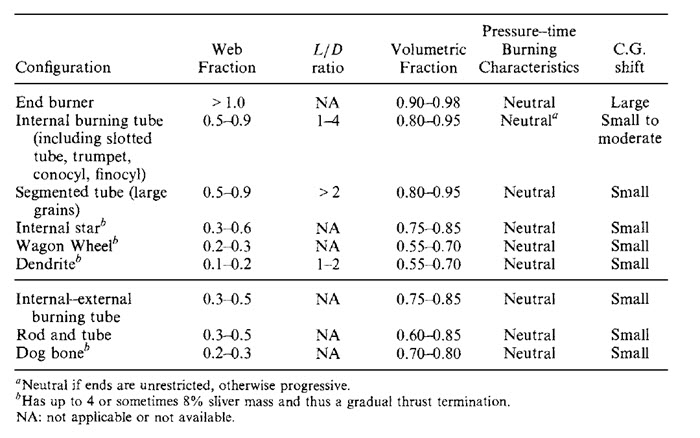
Configurations that combine both radial and longitudinal burning, as does the ‘internal–external burning tube without restricted ends’, are frequently referred to as “three‐dimensional grains” even though all grains are geometrically three‐dimensional. Correspondingly, grains that burn only longitudinally or only radially are called “two‐dimensional grains”. Grain configurations can be classified according to their web fraction bf , their length‐to‐diameter ratio L/D, and their volumetric loading fraction Vf. These three interdependent variables are often used in selecting a grain configuration in the preliminary design of a motor for a specific application.
An end‐burning grain has the highest volumetric loading fraction, the lowest grain cavity volume for a given total impulse, and a relatively low burning area or thrust with a long duration. The internal burning tube is relatively easy to manufacture and can be neutral burning with unrestricted ends of L/D ≈ 2. By adding fins or cones, this configuration works for 2 < L/D < 4. The star configuration is ideal for web fractions of 0.3 to 0.4; it is progressive above 0.4 but can burn neutral with fins or slots. The wagon wheel is structurally superior to the star shape around 0.3 and is a necessary shape for a web fraction of 0.2 (high thrust and short burn time).
Dendrites are used in the lowest web fraction when a relatively large burning area is needed (high thrust and short duration), but stresses may be high. Although the limited number of configurations given in this table may not encompass all the practical possibilities for fulfilling a nearly constant thrust–time performance requirement, combinations of these features may be considered for achieving neutral pressure–time traces and high volumetric loadings before any relatively unproven configuration is accepted.
The capabilities of basic configurations listed in these tables can be extended by alterations. Movements of the center of gravity (CG) influence flight stability of the vehicle. Relative values of this CG shift are also shown in the below table. Most solid propellant manufacturers have specific approaches and sophisticated computer programs for analyzing and optimizing grain geometry alternatives for burn surface and cavity volume analyses.
Characteristics Of Propellant Grain Configurations:
Characteristics Of Several Propellant Grain Configurations
The end‐burning grain (i.e., burning like a cigarette) is unique; it burns solely in the axial direction and maximizes the amount of propellant that can be placed in a given cylindrical motor case. In larger motors (over 0.6 m diameter) these end burners eventually show a progressive thrust curve. The below figure indicates how the burning surface forms a conical shape, causing the rise in pressure and thrust.
Although this behavior is not fully understood, two factors may contribute to higher burning rate near the bondline: chemical migration of the burning rate catalyst into and toward the bondline, and local high propellant stresses and strains at the bond surface, creating local cracks.
Schematic Diagram Of End-Burning Propellant Grain Coning Effect
In larger sizes (above approximately 0.5 m diameter) the burning surface does not remain flat and perpendicular to the motor axis, but gradually assumes a conical shape. The lines in the grain indicate successively larger‐area burning surface contours leading from neutral to progressive burning.
Rocket motors used in air‐launched or in certain surface‐launched missile applications, weather rockets, certain anti‐aircraft or antimissile rockets, and other tactical applications actually benefit by a reducing thrust with burn time. A high thrust is desired to apply the initial acceleration to attain flight‐speed quickly, but, as propellant is consumed and the vehicle mass is reduced, a decrease in thrust is desirable; this limits the maximum acceleration on the rocket‐propelled vehicle and on any sensitive payload, often reduces the drag losses, and usually permits a more effective flight path.
Therefore, there is a benefit to vehicle mass, flight performance, and cost in having a higher initial thrust during the boost phase of the flight, followed by a lower thrust (often 10 to 30% of boost thrust) during the sustaining phase of the powered flight. The below figure shows several grains which give two discrete thrust periods in a single burn operation. The configurations are actually combinations of the configurations listed in the above table.
Several Simplified Schematic Diagrams Of Grain Configurations For An Initial Period Of High Thrust Followed By A Lower‐Thrust Period
In a single‐propellant dual‐thrust level solid rocket motor, factors relating to the sustain flight portion usually dominate in the selection of the propellant type and grain configuration when most of the propellant volume is used during the longer sustain portion.
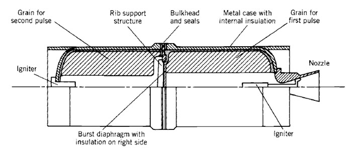
A restartable rocket motor has advantages in a number of tactical rocket propulsion systems used for aircraft and missile defense applications. Here two (or sometimes three) grains are contained inside the same case, each with its own igniter. The grains are physically separated typically by a structural bulkhead or by an insulation layer. One method for accomplishing this is shown in the below figure.
The timing between thrust periods (sometimes called thrust pulses) can be controlled and commanded by the missile guidance system, so as to change the trajectory in a nearly optimum fashion and to minimize the flight time to target. The separation mechanism has to prevent the burning‐hot pressurized gas of the first grain from reaching the other grain and causing its inadvertent ignition. When the second grain is ignited, the separation devices are automatically removed, fractured, or burned, but in such a manner that the fragments of hardware pieces will not plug the nozzle or damage the insulation.
Simplified Diagram Of One Concept For A Two‐Pulse Experimental Rocket Motor With Two Grains Separated By A Bulkhead
During the first pulse operation the metal diaphragm is supported by a spider‐web‐like structure made of high‐temperature material. Upon ignition of the second stage, the scored burst diaphragm is loaded in the other direction; it breaks and its leaves peel back. The bulkhead opening has a much larger area than the nozzle throat.
To find more topics on our website…
Do you want to refer wikipedia? Please click here…

